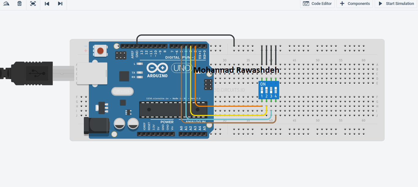

Let’s see an example where number from 0 to 100 is sorted as even and odd number on serial monitor. In your case you would need 3 ICs to get 24 (thus 20) button inputs. Printing even and odd number on serial monitor With one of such IC you can connect 8 buttons, however you can daisy chain max 4 to get 4 8 32 button inputs, only using 4 digital pins of the Arduino. If we have more than one statements then we have to write it in the curly braces otherwise next line will be executed as instruction outside from ‘if’ statement. Also if I press 'PushButton1' again for 2 seconds in Programming mode the Arduino should come out of the programming mode. However, in some cases, this might be reversed. Each case gets selected one after one on the even of 'PushButton1' gets pressed for short time. If we have to execute only one statement after ‘if’ statement then it is our choice to somehow write it as shown in first three conditions. Here are some basic Arduino projects with buttons and LCDs to help you get started.
Arduino button case code#
All syntax of ‘if’ statement in this code are correct. In this code ‘a’ is assigned with 2 and in the setup block serial communication is initialized with 9600 baud rate. put your main code here, to run repeatedly: In particular, a switch statement compares the value of a variable to the values specified in case statements. Syntax of ‘if’ statement looks like this.Ĭondition can be anything like a>2, a=2)//checking if a is greater than or equal to 2 Description Like if statements, switch case controls the flow of programs by allowing programmers to specify different code that should be executed in various conditions. We can or cannot use the else statement with if statement, it just execute the code in it when ‘if’ condition is not true. If statement checks any condition and if it is true then it executes a particular piece of code which is written in the ‘if’ block (in if curly braces or code just next to if statement).

Printing even and odd number on serial monitor.Keypad.addEventListener(keypadEvent) // Add an event listener for this keypad Keypad keypad = Keypad( makeKeymap(keys), rowPins, colPins, ROWS, COLS ) connect to the column pinouts of the keypad This is for an F18 UFC using the control reference for the 'CASE' SendDcsBiosMessage lines. and the code verifies and successfully uploads to the board. DCS BIOS is configured correctly, I get virtual cockpit connection and COMM connection through the correct port etc. When I say it doesn't work, I mean I get zero response, not even ghosting etc. Both methods don't work with IRQ_SERIAL either. I tried wiring buttons individually to pins through a diode (1N4001) with the cathode pointing to the rows, and that didn't work either when I used the generic Control Reference codes in the #define DCSBIOS_DEFAULT_SERIAL.

My matrix is wired like the screenshot attached, the only difference being which pins the rows and columns are connected to (they are wired as per the code below). Tags Enclosure for 6mm tactile button switch 3D prin. Is anyone able to explain why this code below would not communicate with DCS at all? I am using a MEGA2560 board. Click to find the best Results for arduino button Models for your 3D Printer. Animation showing a Arduino Uno and a button hooked up to Pin 2 with a pull.
Arduino button case how to#
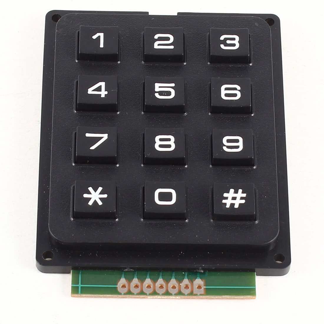
This example turns on the built-in LED on pin 13 when you press the button. Well cover buttons (aka momentary switches), how to use digital input with. Here is a more through explanation of how the keypad works Pushbuttons or switches connect two points in a circuit when you press them. In a keypad matrix you have rows and columns, By alternating the columns between HIGH output and LOW output you can see which of the inputs (rows) are triggered. If you loaded this and watches the SOCAT running without DCS running, you would noticed that in case you ground pin3 then the Arduino would send Which is just setting pin3 HIGH once more.

But DCS-BIOS hasn’t been told this, so what it actually does is it set pin3 HIGH which is like before. A second switch-case example, showing how to take different actions based on. I can interpret that you mean that in case there is connection between 2 & 3 then PVI_0 is value 1, else it’s not. In the Arduino IDE open the serial monitor and send the characters a, b, c. a push button or toggle switch between pin2 and GND) then PVI_0 value would be 1.ĭCS-BIOS Arduino code doesn’t really know what you mean. By using the defaults of DCS-BIOS you don’t get access to a keypad matrix.īasically says to pull pin3 HIGH which would then be PVI_0 value 0. I guess the errors come from case 1 : variables cant be declared inside a case statement the break inside the for doesnt break from the switch statement.


 0 kommentar(er)
